Understanding the Boiler Flue Gas Path in Power Plants
Introduction
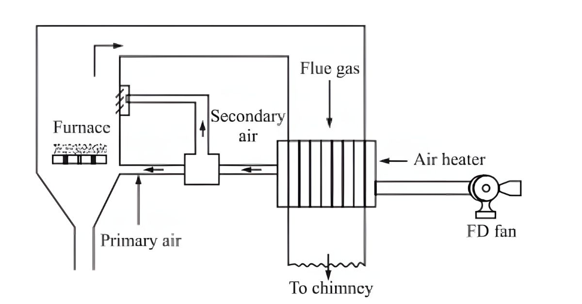
Oxygen is necessary for fuel combustion and comes from atmospheric air. As previously discussed, burning a fixed quantity of fuel requires a specific theoretical amount of air, known as the stoichiometric quantity. Supplying more air than needed causes heat loss, while insufficient air results in incomplete fuel combustion. Therefore, the system must determine the exact quantity of air required to balance heat loss and ensure complete fuel combustion. Before entering the boiler, the system preheats the air used for burning fuel in the furnace. It then delivers this preheated air to the boiler as primary and secondary air.
A forced draught (FD) fan typically supplies air to the boiler. Some boilers also use primary air (PA) fans and secondary air (SA) fans. An induced draught (ID) fan removes the hot flue gas from the boiler.
What is the Boiler Flue Gas Path in a Power Plant?
The Boiler Flue Gas path in a power plant refers to the journey air takes as it moves through various stages of the energy generation process. This system ensures the proper air supply for combustion, supports heat transfer, and facilitates the safe removal of waste gases. Without a well-designed air path, a power plant would struggle to maintain efficiency and meet environmental regulations.
Boiler air Path
To comprehend the intricacies of the air path, one must first understand its primary objectives:
Supplying Combustion Air: Air is crucial for burning fuel, whether it be coal, natural gas, or oil. The oxygen in the air combines with the fuel to release heat energy, which powers turbines and generates electricity.
Heat Transfer Optimization: Preheating and controlling the air improves thermal efficiency, reducing fuel consumption and emissions.
Managing Flue Gases: After combustion, the waste gases must be safely removed and treated to minimize environmental impact
Key Components of the Air Path
To better grasp the air path’s role in a power plant, let’s explore its primary components:
1. Air Intake System
The air intake system is the entry point for fresh air. Filters and intake structures protect the air entering the system from dust, debris, and other contaminants. This step is critical to maintaining the integrity of downstream equipment and ensuring clean combustion.
2. Air Preheaters
Air preheaters play a significant role in improving plant efficiency. They capture heat from the flue gases and warm the incoming air. This process reduces the energy required to heat the air during combustion, enhancing fuel efficiency.
Also, hot air is used for coal drying and conveying in a pulverized boiler. Air is preheated in equipment called air heater or air preheater, placed at the exit end of the flue gas path after the economizer. There are two types of air preheater.
• Regenerative air preheater
• Recuperative air preheater
Regenerative Air Preheater (RAPH)
The Regenerative Air Preheater (RAPH) is a rotating plate-type heat exchanger used in large boilers due to its compact design. It captures heat from exhaust flue gases and transfers it to the combustion air through heat-absorbing metallic elements. These elements are housed in sectors (bisector, tri-sector, or quad sector) within the casing and are replaceable. The rotor, driven by a motor, rotates slowly, alternately exposing elements to hot flue gas and cold air from the FD fan.
The RAPH casing mounts on the boiler structure and connects to the flue gas duct through expansion joints. Thrust bearings support the vertical rotor, while seals prevent leakage. Operators rotate the RAPH before and after boiler operation to prevent thermal stresses. Pulverized boilers widely use tri-sector RAPH to heat both primary air (for coal transport) and secondary air (combustion).
Recuperative Air Preheater
The Recuperative Air Preheater, or static air preheater, is a shell-and-tube heat exchanger. Flue gas flows through the tubes while air flows around the shell. Due to low heat transfer efficiency, the heater requires a large surface area. Baffles are used to optimize air velocity. Cold air enters at the flue gas exhaust end and exits at the inlet end, following a cross-flow pattern. Sometimes, a split-flow design is employed, dividing air into multiple paths. Airboxes manage directional changes in airflow, with configurations varying based on boiler capacity.
3. Combustion Chamber or Boiler
In the combustion chamber, air mixes with fuel to initiate the combustion process. Here, the oxygen from the air reacts with the fuel, releasing thermal energy. This heat is subsequently utilized to produce steam, which powers turbines for electricity generation.
4. Flue Gas Path
Once combustion finishes, the waste gases, called flue gases, flow through a carefully designed path. These gases move through treatment systems such as scrubbers and filters, which remove pollutants before the gases exit into the atmosphere through a chimney or stack.
5. Fans and Blowers
The fan is critical equipment used in a power plant. It is used to produce airflow. Different fans, like ID, FD, PA, SA, Seal air fans, etc., are used in a boil. Forced Draft Fans: Push fresh air into the boiler for combustion.
Centrifugal Fan
In a centrifugal fan, air flows through an inlet duct to the impeller’s centre or eye, which forces it radially outward into the volute or spiral casing from which it flows to a discharge duct. The air changes its direction while entering and leaving the fan. A centrifugal fan suits a smaller flow rate and a significant pressure rise.
Centrifugal fans are available in the following types.
- Radial
- Forward curved
- Backward curved
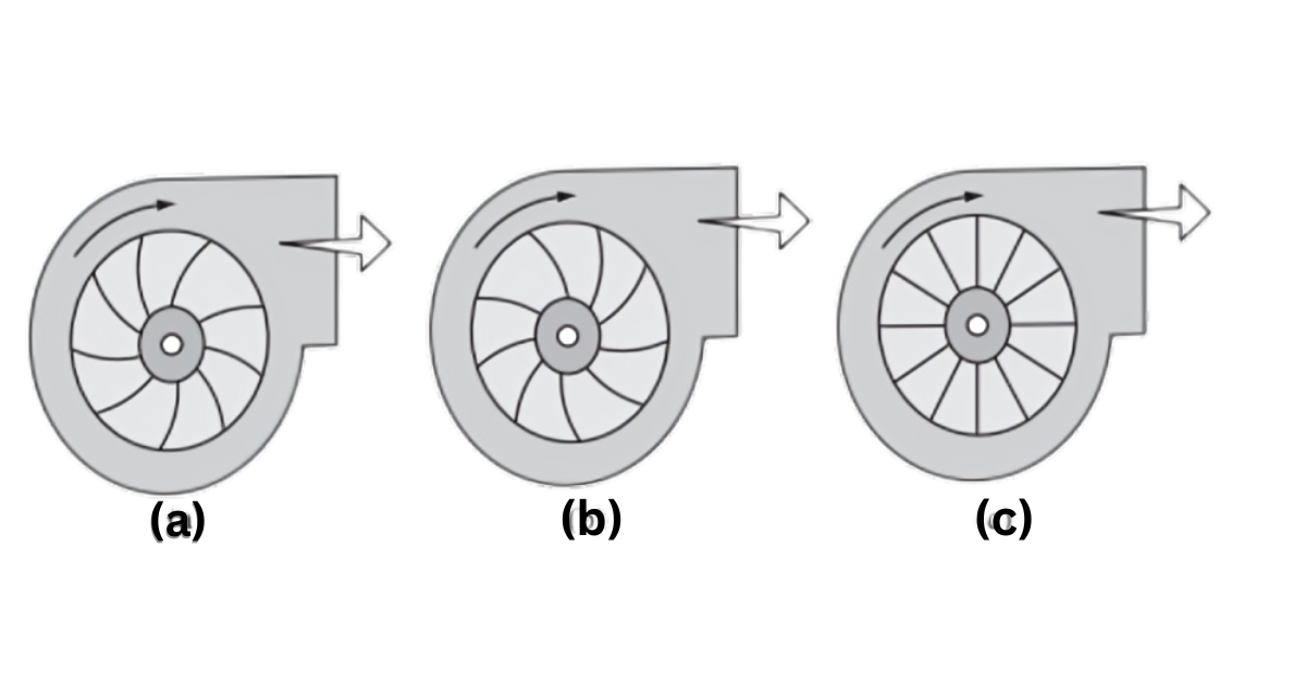
The radial fan is simple in design. This fan is suitable for high static pressure (up to 1400mmwc) application and can handle dusty air at high temperatures. A forward-curved fan is used to handle clean air at lower temperatures. It is suitable for large volumes of air with low pressure. A backward-inclined fan is more efficient than a forward-curved fan.
FD Fan
The Forced Draft (FD) fan is critical in supplying combustion air to the boiler. An electric motor, which may run at a fixed or variable speed, typically powers it. Operators install dampers on the duct’s suction and discharge sides to regulate airflow effectively.
When the fan starts, the motor draws a high inrush current. To reduce the load on the fan during startup, operators keep both the suction and discharge dampers closed. The FD fan pulls fresh air from the atmosphere and pushes it into the boiler. Since the fan handles cold air, its size is smaller than the Induced Draft (ID) fan, which handles hot flue gases.
In balanced draft systems using ID and FD fans, operators always start the ID fan before the FD fan. Some boiler designs include two FD and two ID fans, often referred to as multipass boilers. These fans share the load based on operational needs. Monitoring the fan’s condition is crucial to ensure uninterrupted and efficient operation.
Operators install dampers at both the suction and discharge sides of the fan, which they can operate pneumatically, hydraulically, or electrically. They place a wire mesh at the suction side to stop large particles from entering the fan. The fan’s discharge connects to the boiler via an air duct.
Primary Air and Secondary Air
Oxygen, which is essential for combustion, comes from atmospheric air and is divided into two parts for boiler operation. The first part, primary air, supports the flame and starts combustion. The second part, known as secondary air, enters the furnace to create turbulence and ensure the fuel burns completely.
In pulverized coal-fired boilers, primary air carries pulverized coal into the furnace, while secondary air completes combustion. In FBC boilers, primary air fluidizes and transports fuel, with secondary air supplied over the bed for combustion. Primary air supports the flame for oil and gas-fired boilers, and secondary air ensures fuel combustion. Primary air enters below the fuel bed in stoker and grate-fired boilers, while secondary air ensures complete fuel combustion.
Excess Air
To burn a specific amount of fuel, a certain theoretical amount of air is required, calculated as:
4.35[(8/3 C + 8H2 + S) – O2] kg
However, in practice, operators supply additional air—known as excess air—to ensure complete fuel combustion. Supplying too much air creates a cooling effect, which reduces efficiency. Conversely, insufficient air leads to incomplete combustion, allowing unburned substances to escape through the stack and causing efficiency losses. Therefore, operators must carefully adjust the air supply to achieve complete combustion without introducing excessive air.
An oxygen analyzer monitors excess air by measuring the oxygen percentage in the flue gas. For optimal control, operators should conduct this monitoring online. Efficient fuel usage also relies on measuring CO2 and CO levels in the flue gas; CO2 should be present, not CO.
Excess air requirements vary by boiler type, as shown in the table:
| Type of Boiler | Excess Air (%) | Oxygen (%) |
| Gas-fired | 5%–10% | 1%–2% |
| Oil-fired | 10%–15% | 2%–3% |
| Pulverized coal-fired | 15%–20% | 3%–3.5% |
| Stoker-fired | 20%–30% | 3.5%–5% |
Conclusion
The air path in power plants is a cornerstone of energy generation, ensuring efficient combustion, heat transfer, and emission control. Understanding their components, operation, and significance can help one appreciate the intricate engineering behind modern power plants. As technology evolves, air path systems will continue to improve, contributing to cleaner, more efficient energy production.
In sum, grasping the nuances of the air path—from air intake to flue gas treatment—provides valuable insights into the inner workings of power plants. For those seeking a deeper understanding of how power plants function, exploring the air path offers a fascinating glimpse into the synergy between engineering and energy.
“We greatly appreciate you taking the time to read our article! “Understanding the Boiler Flue Gas Path in Power Plants” To help us reach a wider audience and continue creating valuable content, we kindly ask that you like and share this article on your preferred social media platforms. Your feedback is also invaluable. Please take a moment to leave a comment below, sharing your thoughts and insights on the article in 100 words or less. Your input helps us understand what resonates with our readers and allows us to improve our future content.”