How to Boiler Feed Feedwater Path Works: A Detailed Explanation
Introduction
The heat produced by fuel combustion in a boiler is transferred to the feedwater, generating steam. So, feedwater is the medium to receive heat. Heat transfer takes place from the hot flue gas to the feedwater. If it is a water tube boiler, flue gas moves outside the boiler tube in which feedwater flows.
In a smoke tube boiler, hot gas flows inside the tube, surrounded by feedwater. Feedwater flows continuously into the boiler to extract heat from the flue gas. As steam is continually removed from the boiler, feedwater must be constantly pumped into it.
What is the Feedwater Path?
The feedwater path is a critical process in thermal power plants. It describes the journey of water as it transforms from a simple liquid into high-pressure steam capable of turning turbines and generating electricity. Think of it like a rollercoaster ride of water, full of twists, turns, and stages that prepare it for its big moment—powering the plant.
Power plants use water because it’s an efficient and sustainable medium for transferring heat and generating steam. However, this process requires precision, as water must meet specific conditions to perform effectively without damaging equipment.
DEAERATOR
Boiler feedwater must be pristine—devoid of impurities like suspended solids, minerals, and dissolved gases. In most steam turbine power plants, the steam used to spin the turbine is condensed back into water within a condenser. This condensate then becomes the feedwater, creating a closed-loop system. While this is efficient, some water is inevitably lost through blowdown and leakage, requiring the addition of “make-up” water.
Crucially, feedwater entering the boiler must be completely devoid of dissolved gases, especially oxygen. Oxygen can cause severe corrosion within the boiler, leading to costly repairs and potential safety hazards. This is where the deaerator comes in.
The deaerator plays three vital roles:
- Deaeration: It removes dissolved gases, primarily oxygen, from the feedwater.
- Storage: It acts as a reservoir, storing feedwater before it’s pumped to the boiler.
- Preheating: It uses low-pressure steam to preheat the feedwater, improving boiler efficiency
The Journey of Feedwater: Step-by-Step
1. Water Source
Every journey begins somewhere. For feedwater, the starting point is often a natural source, like a river, lake, or reservoir. The raw water is drawn into the power plant and undergoes initial filtration to remove debris like leaves or sediments.
2. Pre-Treatment
Before the water enters the central system, it must be treated to remove impurities. This step includes processes like:
- Deaeration: Removing dissolved oxygen and gases to prevent corrosion.
- Demineralization: Using ion exchange to remove salts and minerals that could cause scaling inside the system.
3. Boiler Feed Pump
- Feed Pump System and Components
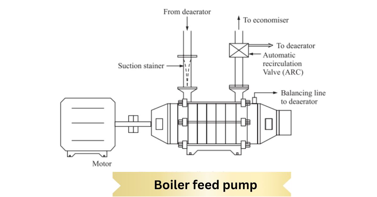
The boiler feed pump’s suction pipe connects to the deaerator storage tank via an isolation valve and a strainer. The suction strainer prevents foreign materials from entering the pump. Differential pressure (DP) across the strainer is monitored to detect clogging. A high DP indicates that the strainer is choked and requires cleaning.
Two mechanical seals are installed at both ends to prevent leakage from the pump’s shaft ends. These seals are cooled using external cooling water, either directly or indirectly. Additionally, because the pump handles hot deaerated water, its shaft can become hot, necessitating cooling water for the bearings.
4. Minimum Flow Protection and Recirculation
Multistage pumps must not operate at zero discharge (i.e., when the discharge valve is closed), which can damage the pump. An automatic recirculation valve (ARC) is installed to ensure a minimum flow rate. If the feed pump flow drops below the required minimum, the ARC opens and recirculates the discharged water to the deaerator through a minimum circulation pipeline.
5. Monitoring and Maintenance
For reliable and trouble-avoid operation, the following parameters are monitored regularly:
- Pump vibrations
- Bearing temperatures
- Pump casing temperature
Pressure Level Steps for Starting a Boiler Feed Pump
To ensure safe and efficient operation, follow these steps when starting a boiler feed pump:
- Ensure power is available to the feed pump.
- Check for the availability of cooling water for gland and bearing cooling.
- Verify that the suction valve is open and the discharge valve is closed.
- Ensure the balancing line and minimum circulation line valves are open.
- Check the pump’s suction pressure.
- Verify the bearing lubricating oil level.
- Start the feed pump and monitor for any abnormal sounds or vibrations.
- Check the bearing and pump casing temperatures.
- If all parameters are normal, slowly open the discharge valve.
- Once the discharge valve is fully open, feed the boiler water.
- Place the standby pump in hot standby mode.
6. Economizer
The economizer is a crucial component in a boiler system that improves efficiency by utilizing waste heat from flue gases. Instead of releasing this hot exhaust directly into the atmosphere, the economizer transfers its heat to the boiler’s feedwater. This reduces fuel consumption and increases the boiler’s overall thermal efficiency boilers overall thermal efficiency.
The economizer is a heat exchanger where flue gas flows through a water tube shell. The hot gas raises the feedwater temperature, increasing its sensible heat. Studies show that lowering the flue gas temperature by 16°C can enhance boiler efficiency by 1% while raising the feedwater temperature by 6°C achieves the same improvement. After the economizer, flue gas flows to the air heater, keeping its temperature above the dew point to avoid corrosion.
Economisers are classified into boiling (steaming) and non-boiling (non-steaming) types. Non-boiling economizers heat water below its saturation temperature, while boiling economizers raise it above. Small or finned tubes are often used to maximize heat transfer.
7. Boiler Drum Level Control
In a boiler, feedwater is continuously evaporated to produce steam, which is extracted. Appropriate water must be pumped in to maintain a safe water level within the boiler. This is done using a boiler feed pump, which helps keep the water level within the desired range in the steam drum.
Some boilers have a single drum, while others have two drums, known as bi-drum boilers. In bi-drum boilers, there is a steam drum and a mud drum (as shown in Figure 9.14). The mud drum is positioned at the bottom of the boiler, and the evaporator tubes connect the two drums.
Once-through boilers do not feature steam or mud drums, so drum-level control is not required in these designs.
In drum-type boilers, the water level in the drum must be regulated to ensure safe and efficient operation. A drum level controller is used to achieve this. This controller adjusts the feedwater flow to maintain the desired drum level by operating a feed control valve, which is typically pneumatically operated and responds to signals from the drum level controller.
There are three main types of drum level controllers:
- Single Element Controller
- Two-Element Controller
- Three-Element Controller
As steam is extracted from the boiler, the drum level decreases. The controller detects this drop and sends a signal to the feed control valve to add the necessary amount of water to restore the level. Each type of controller offers a different method of managing the drum level, and their functions are explained in more detail below.
8. FEED CONTROL STATION
feedwater from the boiler feed pump is sent to the boiler through a control valve. Usually, there are two control valves. One is for a lower load, and the other is for a higher load. One manual bypass valve is also provided for emergencies.
In some boilers, both control valves are capable of 100% load. One is selected for operation, and another is kept on standby. Control valves have two manual isolation valves on both sides for maintenance flexibility. The area where these valves are located is called the feed control station. This section is kept chiefly nearer to the boiler.
9. Evaporator: Steam Formation in Boilers
After passing through the economizer, feedwater enters the boiler drum. Its temperature is still below the saturation point, requiring additional heat to convert it into steam. This heat is provided in the evaporator, where steam formation occurs. Evaporator tubes are typically located in the boiler’s radiation and convection zones.
Water circulates naturally in these tubes due to the density difference between hot and cold water. From the boiler drum, cooler water flows down through downcomer tubes to the bottom distributor, which then directs it to riser tubes placed in the furnace walls (water walls) or the convection zone. Here, the water absorbs heat, forms steam, and returns to the drum.
At higher pressures, the density difference reduces. When water and steam densities equalize at the critical pressure, natural circulation stops, requiring forced circulation. The circulation ratio—water entering downcomers versus steam leaving the circuit—varies with boiler load and heat input, affecting steam generation rates.
10. BLOWDOWN
Due to the continuous evaporation of boiler water, salt concentration in the boiler water increases. Also, due to phosphate treatment, some non-adherent sludge is formed. So, the boiler water’s total dissolved solids (TDS) level increases. To adjust this total dissolved solid level, some boiler water is removed from the boiler, and the same amount of fresh
water is added. By doing so, the concentration of non-desirable dissolved salts is maintained. This process is called the blowdown process, and the water drained out is called the blowdown.
Condensation and Recycling
After the steam works, it cools and condenses back into water. This condensed water, or condensate, is collected and returned to the beginning of the feedwater path. This recycling process reduces water consumption and ensures a continuous loop.
Waterside Scaling and Corrosion
Waterside scaling and corrosion are common issues in boiler systems, impacting efficiency and longevity. Scaling occurs when dissolved minerals in feedwater, such as calcium and magnesium, precipitate under high temperatures and pressures, forming hard deposits on boiler surfaces. These deposits reduce heat transfer efficiency, increase fuel consumption, and may lead to overheating or tube failure.
Corrosion, on the other hand, results from chemical reactions between boiler water and metal surfaces. Common causes include dissolved oxygen, carbon dioxide, and improper water PH. Corrosion weakens the boiler’s metal components, leading to leaks, reduced life span, and potential system failure.
“We greatly appreciate you taking the time to read our article! “A Look at the Feedwater Path” To help us reach a wider audience and continue creating valuable content, we kindly ask that you like and share this article on your preferred social media platforms. Your feedback is also invaluable. Please take a moment to leave a comment below, sharing your thoughts and insights on the article in 100 words or less. Your input helps us understand what resonates with our readers and allows us to improve our future content.”