Pressure Measurement Techniques Used in Power Plants
Introduction
Power plants, the titans of energy production, rely on a delicate balance of intricate systems and precise control. Within this complex web of machinery, accurate and continuous “pressure measurement” is not merely technical; it is paramount for safe, efficient, and reliable operation. From the immense pressures within a boiler to the delicate pressure differentials across turbine stages, precise “pressure determination” is crucial for optimizing plant performance, ensuring safety, and preventing costly equipment failures.

The Significance of Accurate Pressure Readings
Pressure, a fundamental force a fluid exerts, plays a pivotal role in numerous aspects of power plant operation.
Boiler Operation: Maintaining optimal pressure within the boiler is critical for efficient heat transfer and steam generation. Fluctuations in boiler pressure can adversely impact combustion efficiency, leading to increased fuel consumption and potentially damaging the boiler tubes.
Turbine Performance: Precise “pressure readings” across various stages of the turbine are essential for optimizing power output and minimizing wear and tear. Pressure differentials drive the turbine blades, and any deviations from the optimal pressure profile can significantly impact the turbine’s efficiency and lifespan.
Pump Operation: Accurate pressure measurements ensure that pumps operate within their design limits. Maintaining appropriate pressure differentials across pump stages prevents cavitation, which can cause severe damage to pump impellers.
Safety Systems: “Pressure monitoring” plays a crucial role in activating safety systems, such as safety valves and emergency shutdowns. Accurate pressure readings enable timely interventions, preventing equipment failures and mitigating potential hazards.
Control Systems: Pressure measurements provide essential feedback to the plant’s control systems. In real-time, these systems utilize pressure data to adjust operating parameters, such as fuel flow, air-fuel ratios, and steam flow, to maintain optimal performance and efficiency.
A Spectrum of Pressure Measurement Techniques
A diverse array of “pressure measurement techniques” are employed in power plants, each with its unique advantages and applications:
1. Bourdon Tube Pressure Gauge
Typically, pressure gauges are installed at different locations in the boiler and turbine fields. A Bourdon tube-type pressure gauge is mainly used. This type of gauge has a Bourdon tube bent in a circular arc. One end of the Bourdon tube is fixed and connected to the pressure to be measured. The other end of the tube is vacant; when pressure is applied to the tube, the radius of the circular arc increases. 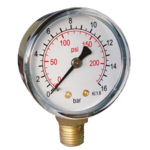
The movement of the unattached end of the Bourdon tube is transmitted to a sector. This section moves a pointer connected to it over a calibrated scale to give a mechanical indication of pressure. When this pressure gauge is used to measure the pressure of hot steam, sufficient care is required so that the burden tube does not come into contact with the hot steam directly. A water-sealing arrangement is made for this. The following two methods are adopted to install a pressure gauge on the hot steam pipeline.
Method 1
In this case, the impulse line is connected to the top of the steam pipeline, and the pressure gauge is fixed at a lower level. Due to the condensation of steam, a water seal is always available.
Method 2
In this case, the impulse line is connected to the top of the steam pipeline, and the pressure gauge is fixed at a higher elevation than the steam pipeline—a loop to collect condensate provided in the impulse line near the pressure gauge.
2. Manometer
A manometer is a simple device to measure pressure. It has a transparent U-tube. This tube is partially filled with either water or mercury. Water and mercury are widely used, as their specific weight for various temperatures is known, and they do not stick to the tube. The pressure to be measured is applied at one end of the manometer tube. Reference pressure (typically atmospheric) is applied to the other end of the tube. When the level of the liquid is balanced, then in that condition.
P2 – P1 = gh
3. Pressure Sensor/Transmitter
The pressure transmitter generates a signal which is proportional to the applied pressure. The applied pressure is, first, converted into mechanical movement in a pressure sensor. This mechanical movement is then converted into an electrical signal. The following techniques are utilized to produce mechanical movement:
• Bourdon tube
• Spring and piston
• Bellows and capsule
• Diaphragm
• Strain gauge
The Bourdon tube principle has been explained in The Bourdon tube movement due to applied pressure acting as a pressure sensor. In the spring and piston method, pressure is applied to a piston, which moves against the compression of the spring. The position of the piston is proportional to the applied pressure—a spring and piston-type pressure sensor. In the case of bellows and capsules, when pressure is applied to a closed bellow, then the bellow expands and produces mechanical movement proportional to the applied pressure.
A diaphragm-type pressure transmitter is used chiefly for process pressure measurement. When pressure is applied to the thin diaphragm, it expands. This movement of the diaphragm is utilized to measure the pressure. In the strain gauge principle, the mechanical movement changes the length of an element. This movement of the elements can be used to alter the electrical resistance. The mechanical movement obtained in the above sensor is converted into an electrical signal.
The following methods are used to get an electrical signal from the mechanical movement:
• Piezoelectric method
• Capacitive method
-
Piezoelectric Method
A piece of crystalline material is used for this type of pressure transmitter. Certain substances generate voltage when they are subjected to mechanical forces or stress. These circumstances are generally crystalline and are available in the following two types
• Natural
• Synthetic
Natural crystallines are quartz and tourmaline, and synthetic crystals include Rochelle salts, barium nitrate, and ammonium dihydrogen phosphate (ADP). When mechanically stressed, crystalline material produces an electric charge on its surface, which is measured. The crystalline material is noted due to the mechanical movement of the sensor, as discussed earlier.
-
Capacitive Method
In this method, the mechanical movement of the sensor changes the capacitance of an electronic component, which produces an output signal proportional to the pressure applied
• It has memory.
• It can be programmed.
• It can convert analog signal to digital.
• This can perform calculations.
• A smart transmitter can diagnose self-faults.
• It can communicate with remote locations.
• This is less sensitive to the effect of temperature and humidity.
This transmitter is preferred over the simple electronic transmitters. Both analog and digital output signals are obtained from this transmitter. Typically, this transmitter obtains a four mA–20 mA output signal. This signal is less affected by the electrical disturbances.
With the help of a communicator, testing, configuring, feeding, or acquiring data can be done. Communicator is a handheld interface device that allows digital instructions. The communicator can be connected directly to the smart transmitter or in parallel anywhere in the loop. Mostly, variable capacitance (diaphragm) and variable resistance (strain gauge or piezoelectric)
methods are used for the primary sensing of the transmitter.
4. Absolute Pressure
One sensor port is subjected to pressure, while the other is kept open to the atmosphere to measure the gauge pressure.
5. Gauge Pressure
When used to measure absolute pressure, one transmitter port is closed (welded or vacuum sealed). When pressure is applied to the other port, it indicates absolute pressure.
6. Differential Pressure (DP)
Pressure is applied at both ports to measure the differential pressure. The transmitter indicates the difference between two applied pressures. Smart pressure transmitters are mounted on manifolds. The manifolds are available in the following three types:
• Two-valve manifold
• Three-valve manifold
• Five-valve manifold
Conclusion
Accurate “pressure measurement” is not merely technical but a cornerstone of reliable and efficient power plant operation. Power plant operators can optimize performance, enhance safety, and minimize downtime by employing a judicious selection of “pressure measurement techniques” and implementing robust monitoring and control systems. Continuous advancements in sensor technology and data analysis will further refine “pressure measurement techniques” and drive the evolution of more efficient and sustainable power generation systems.
“We greatly appreciate you taking the time to read our article! “Pressure Measurement Techniques Used in Power Plants” To help us reach a wider audience and continue creating valuable content, we kindly ask that you like and share this article on your preferred social media platforms. Your feedback is also invaluable. Please take a moment to leave a comment below, sharing your thoughts and insights on the article in 100 words or less. Your input helps us understand what resonates with our readers and allows us to improve our future content.”